Lab 11 - Localization
Robot localization with known map

1. Activity Identity
| Activity title | Introduction to Robotics |
|---|---|
| Topic | Robotics / ROS 2 / Localization |
| Authors | Institute of Robotics and Machine Intelligence Dominik Belter, Jakub Chudziński, Marcin Czajka, Kamil Młodzikowski |
| Target learners | Bachelor |
| Estimated duration | 1.5 hours |
| Difficulty level | Intermediate |
| FOSSBot environment | Simulator (can be also performed on a real robot) |
| Licence | CC BY 4.0 |
2. Learning Objectives and Competences
| ID | Learning outcome | Related competences | Assessment evidence |
|---|---|---|---|
| LO1 | Students will be able to understand and use ROS2 lifecycle nodes in a navigation stack, including map_server and AMCL activation. | ROS2 architecture / lifecycle management / system integration | Terminal logs showing lifecycle transitions (configure, activate) |
| LO2 | Students will be able to interpret AMCL output and understand how robot pose is estimated in a global map frame. | Probabilistic robotics / state estimation / spatial reasoning | Terminal output from /amcl_pose and AMCL pose monitoring node |
| LO3 | Students will be able to implement a ROS2 subscriber node in Python to process and display real-time localization data from AMCL. | ROS2 communication / Python programming / data processing | Source code of AMCL pose monitoring node and execution logs |
3. Prerequisites
Basic knowledge of Python programming.
Basic familiarity with Linux terminal and ROS2 command-line tools.
Basic understanding of ROS2 concepts (nodes, topics, services, transforms, and launch files).
Basic understanding of mobile robot localization concepts, including odometry, LiDAR sensors, and occupancy grid maps.
Familiarity with ROS2 visualization tools (e.g., RViz2) for inspecting maps, laser scans, TF frames, and robot pose estimates.
Ability to capture evidence, such as screenshots, terminal logs, or observation tables.
4. Required Material and Setup
| Category | Item | Version / Quantity | Notes |
|---|---|---|---|
| Hardware | Workstation | 1 per student | Linux PC with at least 8 GB RAM. An NVIDIA GPU with the
nvidia-container-toolkit is recommended so that
start_container.sh can use GPU passthrough; on a machine
without an NVIDIA GPU, use the included
start_container_no_gpus.sh instead. |
| Software | Docker Engine | 24.0 or newer | Pre-installed on the lab workstations. |
| Software | FOSSBotEduSim simulator | latest from main branch |
Cloned from https://github.com/LRMPUT/FOSSBotEduSim
(instructions available in the repository). The repository ships its own
Dockerfile that derives from the official
osrf/ros:jazzy-desktop-full image and pre-installs every
ROS 2 package the lab needs. |
5. Safety, Ethics and Accessibility Notes
If using a physical robot: When teleoperating the physical robot for mapping, follow the robot to ensure it does not bump into anything or fall down. Ensure batteries are safely charged.
6. Scenario and Problem Statement
Autonomous mobile robots must be able to estimate their position within a known environment in order to navigate safely and reliably. One of the most common approaches is localization using an occupancy grid map, where the environment is represented as a grid of cells, each indicating whether it is free, occupied, or unknown. By combining sensor measurements (e.g., LiDAR) with odometry and the pre-built map, the robot can continuously estimate its pose within the environment.
In this lab, you will use a simulated robot operating in a known environment and perform map-based localization using the ROS2 Navigation Stack. You will configure and launch the localization module (AMCL), initialize the robot’s pose, and verify that the estimated position converges to the robot’s true location. You will then analyze the localization performance by observing the robot’s estimated pose, the particle cloud, and the transformation between the map and odom coordinate frames under different operating conditions.
7. Lab Workflow
| Phase | Student action | Expected output | Time |
|---|---|---|---|
| 1. Prepare | Install/check ROS2 + Nav2 + AMCL environment | Ready-to-run setup | [5 min] |
| 2. Setup | Launch simulator, robot model, and verify TF tree | Simulator running | [5 min] |
| 3. Mapping / Localization setup | Load map with map_server and initialize AMCL localization | An occupancy grid map + initial pose estimate required | [10 min] |
| 4. AMCL pose inspection | Subscribe to /amcl_pose and verify real-time localization output | Results table | [20 min] |
| 5. Segment checking service | Implement Python node subscribing to AMCL pose and printing processed data | Working ROS2 subscriber node + execution logs | [40 min] |
| 6. Reflect | Answer synthesis questions | Short analysis | [10 min] |
8. Step-by-Step Instructions
Step 1 - Environment preparation
Check if you have the FOSSBot ros2 environment set up (if not, install it following the instructions available in the repository).
Start the FOSSBotEduSim container.
bash start_container.shor if you are on a machine without an NVIDIA GPU, use:
bash start_container_no_gpus.sh- [Only if you’re not using the Docker container] Open a terminal and source the ROS2 setup file:
source /opt/ros/jazzy/setup.bashThe Docker image added the ROS2 setup file to your
.bashrc, so if you are using the container, you don’t need
to run this command.
Step 2 - Simulator configuration and odometry localization
- Launch the FOSSBot simulator with the single wall world:
ros2 launch fossbot_educational_description single.launch.py world:=sample_rooms.sdfEnsure that in Gazebo you can see the robot, the blue walls and that RViz is running.
Open a new terminal and enter the docker container using command:
docker exec -it ros2_fossbot_edu bashLaunch the tf2 (transformation) module that shows the frames of the robot
ros2 run tf2_tools view_framesThis command listens tf2 transformations and displays them as a graph. Check the generated pdf files. Currently, the robot uses wheeled odometry to estimate its position. It counts the rotations of the wheeels (like a car or bike) and its kinematic model to estimate x, y, and yaw angle. You should see the following transformation:
odom -> base_footprint -> base_link -> top_mount -> lidar_base -> lidar -> lidar_scan_frame
Each arrow represents SE3 transformation (translation x,y,z and rotation around each axis). The wheeled odometry estimates the position of the base_footprint with respect to the odom frame.
- Open another new terminal and enter the docker container. Start teleoperation of the robot using the keyboard:
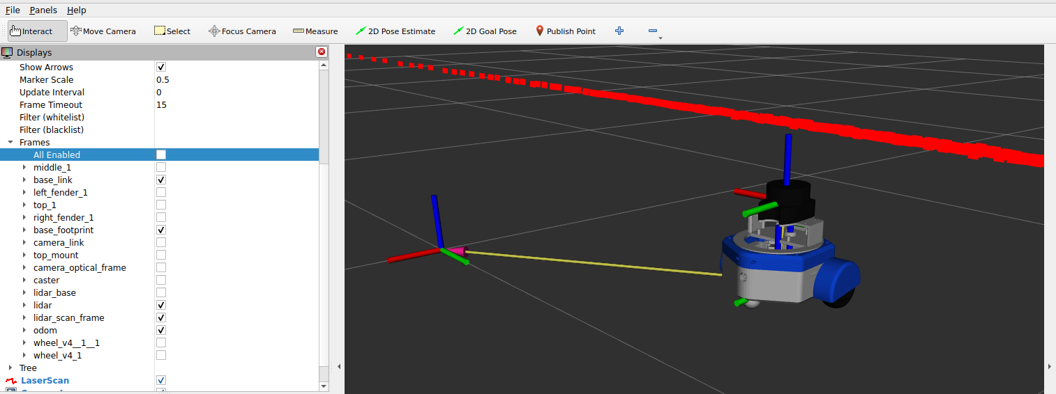
ros2 run teleop_twist_keyboard teleop_twist_keyboard- Drive the robot around to see the tf2 transformations. You can display the tf frames in the RViz2. The results should look like this:
Expected result:
Step 3 - Adaptive Monte Carlo Localization (AMCL) in ROS2
Restart the simulation so the robot start in the initial configuration
Got the the RViz2 and change “fixed frame” option to “map”. Start the map server with a map saved in the previos tutorial (Lab 10 - mapping):
ros2 run nav2_map_server map_server --ros-args -p yaml_filename:=sample_rooms_map.yaml -p use_sim_time:=trueBoth map_server and amcl are ROS2 lifecycle nodes. This means they do not start publishing data immediately after being launched. Instead, they go through a controlled state machine with the following stages:
unconfigured -> inactive -> active
When the node is first started, it is in the unconfigured state and does not perform its main function. Therefore, it must be explicitly transitioned to the active state using lifecycle commands in another terminal:
ros2 lifecycle set /map_server configure
ros2 lifecycle set /map_server activate
Expected result:
The map should look like this: 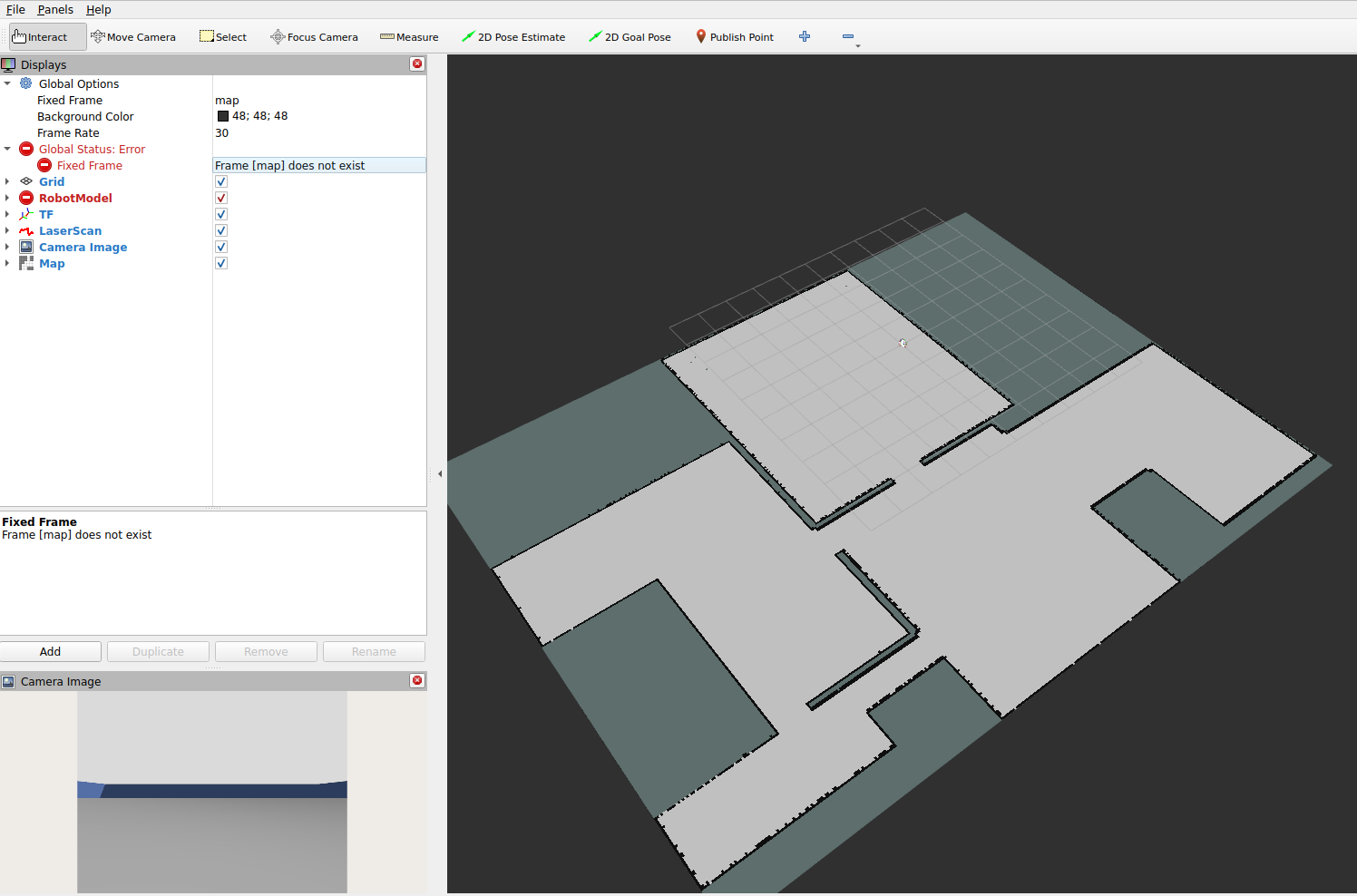
The robot is white and the RViz returns multiple warning because the position of the robot with respect to the map is unknown. This is why we need the localization module - to know the position of the robot with respect to the known map.
- Run AMCL localization node:
ros2 run nav2_amcl amcl --ros-args --params-file minimal_amcl.yaml -r scan:=/scan -r tf:=/tfand in another terminal:
ros2 lifecycle set /amcl configure
ros2 lifecycle set /amcl activate
AMCL (Adaptive Monte Carlo Localization) is a probabilistic localization algorithm used in mobile robotics to estimate a robot’s pose (position and orientation) within a known map. It uses a particle filter to represent multiple hypotheses of the robot’s location and continuously updates them using sensor measurements, typically from a LiDAR or laser scanner. By combining odometry data with scan matching against an occupancy grid map, AMCL refines the particle distribution over time, converging toward the most likely robot pose. It is widely used in ROS-based navigation systems because it is robust to sensor noise and can recover from localization errors such as the “kidnapped robot” problem.
- Testing the localization node. You should initialize the pose of the robot with respect to the map. Use the “2D Pose Estimate” button to set the initial pose of the robot:

If you do this carefully (required) you should see the laser scan
(red dots) aligned with the map: 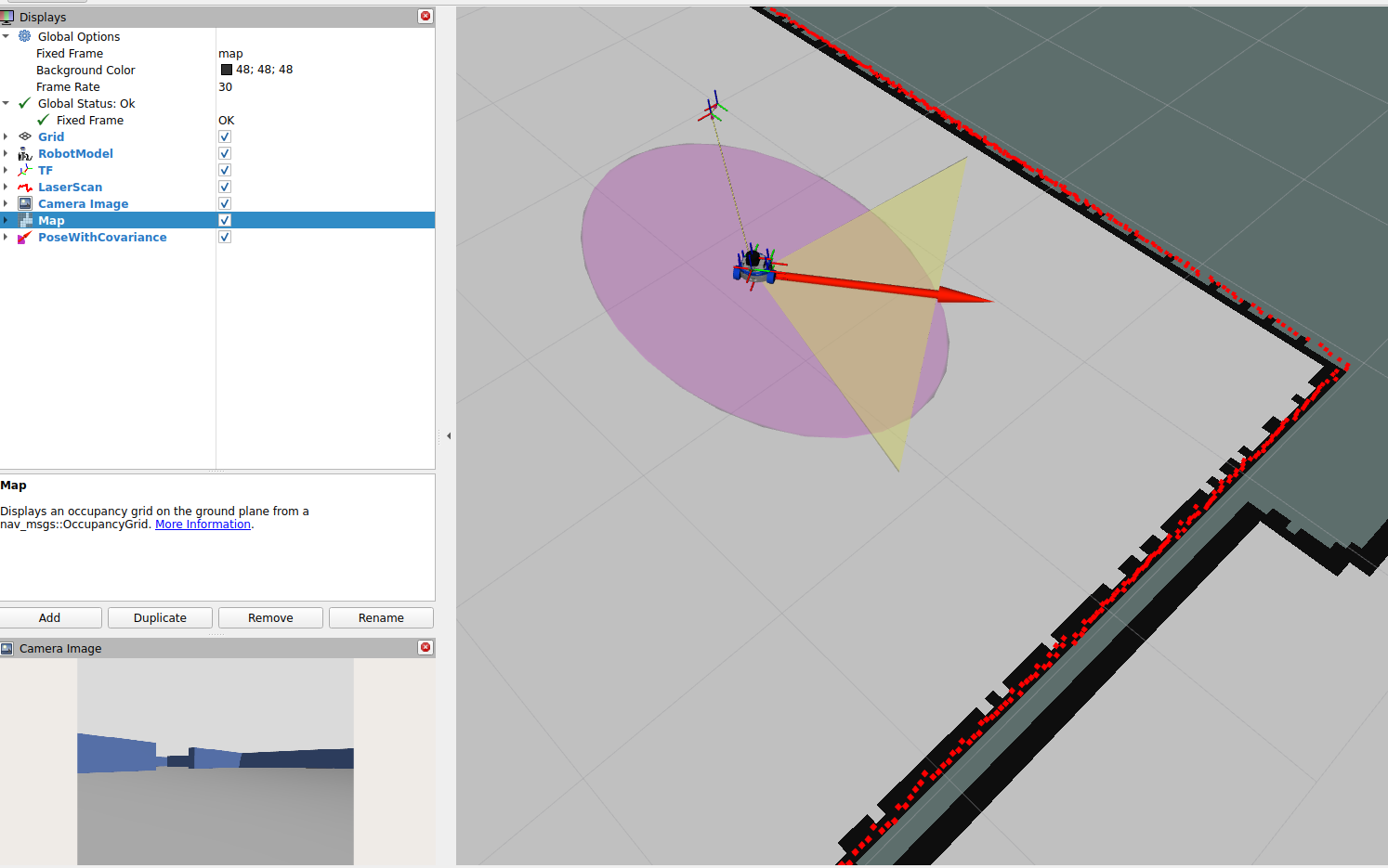
The purple ellipsoid represents the pose uncertainty and if the module works properly, the ellipsoid should be small.
- Open a new terminal and launch the tf2 (transformation) module that shows the frames of the robot
ros2 run tf2_tools view_framesThis command listens tf2 transformations and displays them as a graph. Check the generated pdf files. Currently, the robot uses both, wheeled odometry and AMCL to estimate its position. You should see the following transformation:
map -> odom -> base_footprint -> base_link -> top_mount -> lidar_base -> lidar -> lidar_scan_frame
In the current version the AMCL intruduces correction to the odometry estimation indicated as “map -> odom”. This comes from the fact that each tf2 frame can have only one parent frame. Thus, the robot can’t estimate its position from two sources. They have to be organized in a chain.
Step 4 - checking current pose of the robot
❗❗IMPORTANT:❗❗: Do not close the terminal with the simulator and AMCL. It will be needed in the next steps.
- AMCL continuously estimates the robot’s pose in the map frame and publishes it as a ROS2 topic. The estimated pose is available on:
/amcl_poseThis topic contains a geometry_msgs/PoseWithCovarianceStamped message, which includes:
estimated robot position (x, y) orientation (quaternion) uncertainty (covariance matrix)
- To check the current estimated pose directly from the terminal, open a new terminal and enter the Docker container:
docker exec -it ros2_fossbot_edu bashThen subscribe to the AMCL pose topic:
ros2 topic echo /amcl_poseYou should see continuous updates similar to:
header: frame_id: “map” pose: pose: position: x: … y: … z: 0.0 orientation: x: … y: … z: … w: …
- To observe only the most recent pose (without continuous streaming), you can use:
ros2 topic echo /amcl_pose --onceYou can also inspect the publishing rate of the AMCL pose estimate:
ros2 topic hz /amcl_poseThis helps verify that AMCL is actively updating the localization estimate.
Expected result:
The terminal shows continuously updated robot pose estimates. The position changes when the robot moves. The covariance increases when localization is uncertain and decreases when AMCL converges. RViz shows the robot pose aligned with the map when localization is successful.
Step 5 - Implementing a ROS2 node to read AMCL pose and print it in the terminal
- In this step, you will create a ROS2 node that subscribes to the AMCL pose topic (/amcl_pose) and continuously prints the robot’s estimated position in the terminal.
The node will:
subscribe to /amcl_pose extract x, y position print values in a clean format update whenever AMCL publishes a new estimate First, create a new ROS2 Python package:
cd /fossbot_ros2/ws_fossbot/src
ros2 pkg create --build-type ament_python amcl_pose_monitor
Create a new Python file for the node:
touch /fossbot_ros2/ws_fossbot/src/amcl_pose_monitor/amcl_pose_monitor/amcl_pose_monitor.pyPaste the following code into amcl_pose_monitor.py:
#!/usr/bin/env python3
import rclpy
from rclpy.node import Node
from geometry_msgs.msg import PoseWithCovarianceStamped

class AMCLPoseMonitor(Node):
    def __init__(self):
        super().__init__('amcl_pose_monitor')

        # Subscribe to AMCL pose
        self.subscription = self.create_subscription(
            PoseWithCovarianceStamped,
            '/amcl_pose',
            self.pose_callback,
            10
        )

    def pose_callback(self, msg):
        x = msg.pose.pose.position.x
        y = msg.pose.pose.position.y

        self.get_logger().info(f"AMCL Pose -> x: {x:.3f}, y: {y:.3f}")


def main(args=None):
    rclpy.init(args=args)
    node = AMCLPoseMonitor()
    rclpy.spin(node)
    node.destroy_node()
    rclpy.shutdown()


if __name__ == '__main__':
    main()
Register the node in setup.py by adding the following entry:
entry_points={
    'console_scripts': [
        'amcl_pose_monitor = amcl_pose_monitor.amcl_pose_monitor:main'
    ],
},
Add dependencies to package.xml:
<exec_depend>rclpy</exec_depend>
<exec_depend>geometry_msgs</exec_depend>
Build the package:
cd /fossbot_ros2/ws_fossbot
colcon build --symlink-install --packages-select amcl_pose_monitor
source install/setup.bash
Run the node:
ros2 run amcl_pose_monitor amcl_pose_monitorExpected result:
When you move the robot with the teleoperation module, the terminal prints AMCL pose updates. Output looks like:
AMCL Pose -> x: 1.234, y: -0.456 AMCL Pose -> x: 1.240, y: -0.460 AMCL Pose -> x: 1.250, y: -0.470
This confirms that AMCL localization is working correctly and is being consumed by a custom ROS2 node.
9. Analysis Questions
AMCL uses a particle filter to estimate robot pose in a known map. Why is a probabilistic approach useful in real robotic systems where sensor noise and motion uncertainty are present?
AMCL assumes a mostly static environment represented by an occupancy grid. What problems can arise in real environments where people or objects move, and how might this affect the stability or convergence of the localization result?
10. Submission Requirements
Completed source code for the ROS2 package implementing the AMCL pose monitoring node from Step 5 (subscriber to /amcl_pose).
Screenshots or terminal logs showing the AMCL node running and publishing pose estimates in real time.
Evidence of successful localization in RViz (map, laser scan alignment, and robot pose estimate after initialization with 2D Pose Estimate).
Short answers to the analysis questions.
11. References and Open Licence
[Add references, datasets, libraries, repositories, and licensing information. Mention original authors where applicable.] - Geometry messages documentation in ROS2: https://docs.ros.org/en/jazzy/p/geometry_msgs/, - Nav2 Documentation: https://nav2.org/.
The Creative Commons Attribution 4.0 International (CC BY 4.0) license allows users to share, copy, distribute, and adapt the work, even for commercial purposes, as long as proper credit is given to the original creator.
EU funding disclaimer
Funded by the European Union. Views and opinions expressed are however those of the author(s) only and do not necessarily reflect those of the European Union or the European Education and Culture Executive Agency (EACEA). Neither the European Union nor EACEA can be held responsible for them.